Operating Voltage
Operating Voltage
PI Ceramic offers various types of piezo actuators with different layer thicknesses. This results in nominal operating voltages of 60 V for PICMA® bender actuators and up to 1000 V for PICA actuators.
Electrical Behavior
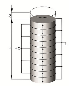
At operating frequencies well below the resonant frequency, a piezo actuator behaves like a capacitor. The actuator displacement is proportional to the stored electrical charge, as a first order estimate. The capacitance of the actuator depends on the area and thickness of the ceramic as well as the material properties. In the case of actuators that are constructed of several ceramic layers electrically connected in parallel, the capacitance also depends on the number of layers. In the actuators there are leakage current losses in the μA range or below due to the high internal resistance.
Electrical Capacitance Values
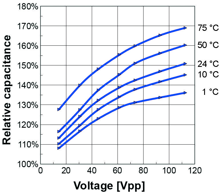
The actuator capacitance values indicated in the technical data tables are small-signal values, i.e. measured at 1 V, 1000 Hz, 20 °C, unloaded. The capacitance of piezo ceramics changes with the voltage amplitude, the temperature and the mechanical load, to up to 200 % of the unloaded, small-signal, room-temperature value.
For calculations under large-signal conditions, it is often sufficient to add a safety factor of 70 % to the small-signal capacitance (fig. 2).
| C | Capacitance [F] |
| n | Number of ceramic layers in the actuator |
| ε33T | Permittivity = ε33/ε0 [As/Vm] |
| A | Actuator cross-sectional area [m²] |
| hL | Layer thickness in the actuator [m] |
| l | Actuator length [m] |
| P | Power converted into heat [W] |
| V | Voltage on the piezo actuator [V] |
| Vpp | Piezo voltage (peak-to-peak) [V] |
Accordingly, a PICMA® stack actuator with a layer thickness of 60 µm has an approx. 70 times higher capacitance than a PICA stack actuator of the same volume and a layer thickness of 500 µm. The electric power consumption P of both types is roughly the same due to the relationship P ~ C V2 since the operating voltage changes proportionally to the layer thickness.
When electrically charged, the amount of energy stored in a piezo actuator is approximately E = 0.5 CV2 . Every change in the charge (and therefore in displacement) is connected with a charge transport that requires the following current I:
![Current [A] Current [A]](/fileadmin/user_upload/pi_ceramic/IMG/PIC_Gleichung_23.png)
Slow position changes only require a low current. To hold the position, it is only necessary to compensate for the very low leakage currents, even in the case of very high loads. The power consumption is correspondingly low. Even when suddenly disconnected from the electrical source, the charged actuator will not make a sudden move. The discharge and thus the return to zero position will happen continuously and very slowly.
Operation with Position Control
In closed-loop operation, the maximum safe operating frequency is also limited by the phase and amplitude response of the system. Rule of thumb: The higher the resonant frequency of the mechanical system, the higher the control bandwidth can be set. The sensor bandwidth and performance of the controller (digital or analog, filter and controller type, bandwidth) also limit the operating bandwidth of the positioning system.
Power Consumption of the Piezo Actuator
In dynamic applications, the power consumption of the actuator increases linearly with the frequency and actuator capacitance. A compact piezo actuator with a load capacity of approx. 100 N requires less than 10 W of reactive power at 1000 Hz and 10 μm stroke, whereas a high-load actuator (>10 kN load) requires several 100 W under the same conditions.
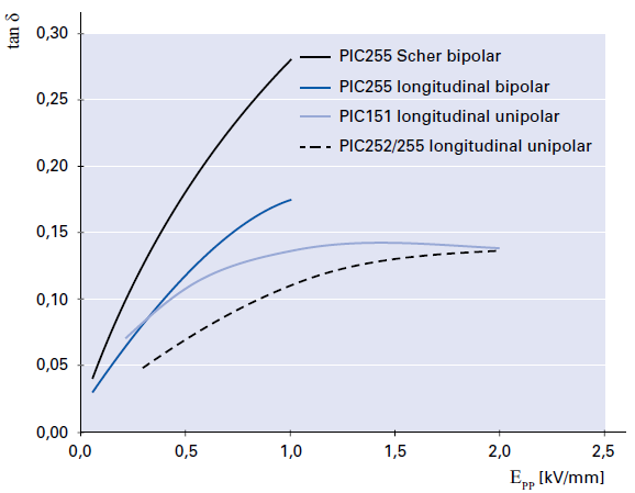
For actuator piezo ceramics under small-signal conditions, the loss factor is on the order of 0.01 to 0.02. This means that up to 2 % of the electrical power flowing through the actuator is converted into heat. In the case of large-signal conditions, this can increase to considerably higher values (fig. 3). Therefore, the maximum operating frequency also depends on the permissible operating temperature. At high frequencies and voltage amplitudes, cooling measures may be necessary. For these applications, PI Ceramic also offers piezo actuators with integrated temperature sensors to monitor the ceramic temperature.
| P | Power converted into heat [W] |
| tan δ | Dielectric loss factor (ratio of effective to reactive power) |
| f | Operating frequency [Hz] |
| C | Actuator capacitance [F] |
| Vpp | Piezo voltage (peak-to-peak) [V] |
| Epp | Electric field strength (peak-to-peak) [kV/mm] |
The average current, peak current, and small signal bandwidth for each piezo amplifier from PI can be seen from the specifications in the >> Data Sheets.
Dielectric Loss Factors
Fig. 3 shows the dielectric loss factors tan δ for different materials and control modes at room temperature and with quasistatic control. The conversion between voltage and field strength for specific actuators is done with the layer thicknesses. The actual loss factor in the component depends on further factors such as the mechanical preload, the temperature, the control frequency, and the amount of passive material.
Continuous Dynamic Operation
To be able to operate a piezo actuator at the desired dynamics, the piezo amplifier must meet certain minimal requirements. To asses these requirements, the relationship between amplifier output current, operating voltage of the piezo actuator, and operating frequency has to be considered.
A secondary constraint that applies here is that the amplifier must be capable of delivering at least Imax = 2 Ia for the charging time, i.e. for half the period. If this is not feasible, an appropriately lower maximum operating frequency should be selected. For amplifiers which cannot deliver a higher peak current or not for a sufficient period of time, the following equation should be used for calculation instead:
Signal Shape and Bandwidth
In addition to estimating the power of the piezo amplifier, assessing the small-signal bandwidth is important with all signal shapes that deviate from the sinusoidal shape.
The less the harmonics of the control signal are transferred, the more the resulting shape returns to the shape of the dominant wave, i.e. the sinusoidal shape. The bandwidth should therefore be at least ten-fold higher than the basic frequency in order to prevent signal bias resulting from the nontransferred harmonics.
In practice, the limit of usable frequency portions to which the mechanical piezo system can respond is the mechanical resonant frequency. For this reason, the electrical control signal does not need to include clearly higher frequency portions.
The fastest displacement of a piezo actuator can occur in 1/3 of the period of its resonant frequency. Response times in the microsecond range and accelerations of more than 10,000 g are feasible, but require particularly high peak currents from the piezo amplifier. This makes fast switching applications such as injection valves, hydraulic valves, switching relays, optical switches, and adaptive optics possible.
For charging processes with constant current, the minimal rise time in pulse-mode operation can be determined using the following equation:
As before, the small-signal bandwidth of the amplifier is crucial. The rise time of the amplifier must be clearly shorter than the piezo response time in order not to have the amplifier limit the displacement. In practice, as a rule-of-thumb, the bandwidth of the amplifier should be two- to three-fold larger than the resonance frequency.
Advantages and Disadvantages of Position Control in Switching Applications
A closed-loop controller always operates in the linear control range of voltages and currents. Since the peak current is limited in time and is therefore nonlinear, it cannot be used for a stable selection of control parameters. As a result, position control limits the bandwidth and does not allow for pulse-mode operation as described.
In switching applications, it may not be possible to attain the necessary positional stability and linearity with position control. Linearization can be attained, e.g., by means of charge-controlled amplifiers or by numerical correction methods.
![Capacitance [F] at a fixed actuator length l Capacitance [F] at a fixed actuator length l](/fileadmin/user_upload/pi_ceramic/IMG/PIC_Gleichung_22.png)
![Capacitance [F] Capacitance [F]](/fileadmin/user_upload/pi_ceramic/IMG/PIC_Gleichung_21.png)
![Power converted into heat [W] Power converted into heat [W]](/fileadmin/user_upload/pi_ceramic/IMG/PIC_Gleichung_24.png)
![Maximum operating frequency [Hz] Maximum operating frequency [Hz]](/fileadmin/user_upload/pi_ceramic/IMG/PIC_Gleichung_27.png)
![Maximum operating frequency [Hz] Maximum operating frequency [Hz]](/fileadmin/user_upload/pi_ceramic/IMG/PIC_Gleichung_28.png)
![Average current of the amplifier (source/sink) [A] Average current of the amplifier (source/sink) [A]](/fileadmin/user_upload/pi_ceramic/IMG/PIC_Gleichung_25.png)
![Peak current of the amplifier (source/sink) [A] Peak current of the amplifier (source/sink) [A]](/fileadmin/user_upload/pi_ceramic/IMG/PIC_Gleichung_26.png)
![Time until Vpp is applied to the piezo actuator [s] Time until Vpp is applied to the piezo actuator [s]](/fileadmin/user_upload/pi_ceramic/IMG/PIC_Gleichung_29.png)
